A MUSEUM OF WATCHMAKING
AUTOMATIC WINDING / STATIC STUDY

Rolex
3235

Automatic winding module
2016 illustration baseline · estimated geometry

Drag to rotate · Scroll to zoom · Double-click a part to inspectKeyboard: arrows select · Enter inspects · Escape returns

Select a part to inspect
Compare two views

Remember this view, explore another, then swap between them. Both show the same model.

No view remembered.

AEVO FIELD STUDY — 001ROLEX / DATEJUST / CALIBRE 3235

THE WATCH.
THE WORK
within.

A familiar face. An intricate world behind it. Our reconstruction begins with the Datejust 41, reference 126334.

Discover what lies inside
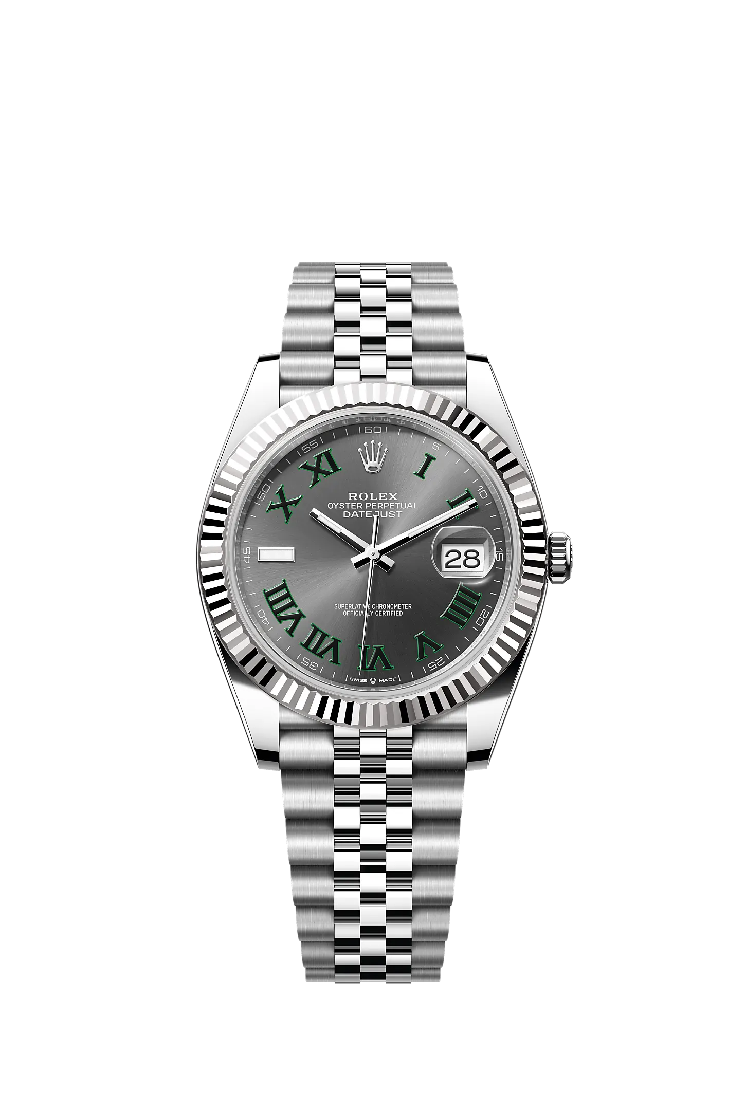
Rolex Datejust 41 reference 126334, slate Wimbledon dial and Jubilee bracelet
Official product image unavailable. View the Datejust on Rolex ↗
Rolex product image · 126334-0022, slate “Wimbledon” dial / Jubilee bracelet. © Rolex.
126334 / DATEJUST 41THE WATCH → THE MODEL → THE EVIDENCE
THE CALIBRE INSIDE THE 126334
3235

From the wrist
to the winding system.

Rolex identifies the 3235 as the movement inside this Datejust. We begin with its automatic winding module: the weight, supports and wheels that connect wrist movement to winding.

41 MMCASE DIAMETER
~70 HPOWER RESERVE
↔BIDIRECTIONAL WINDING

Rolex · model specifications ↗

ONE CALIBRE / FIVE EXPRESSIONS

Different lives.
The same calibre.

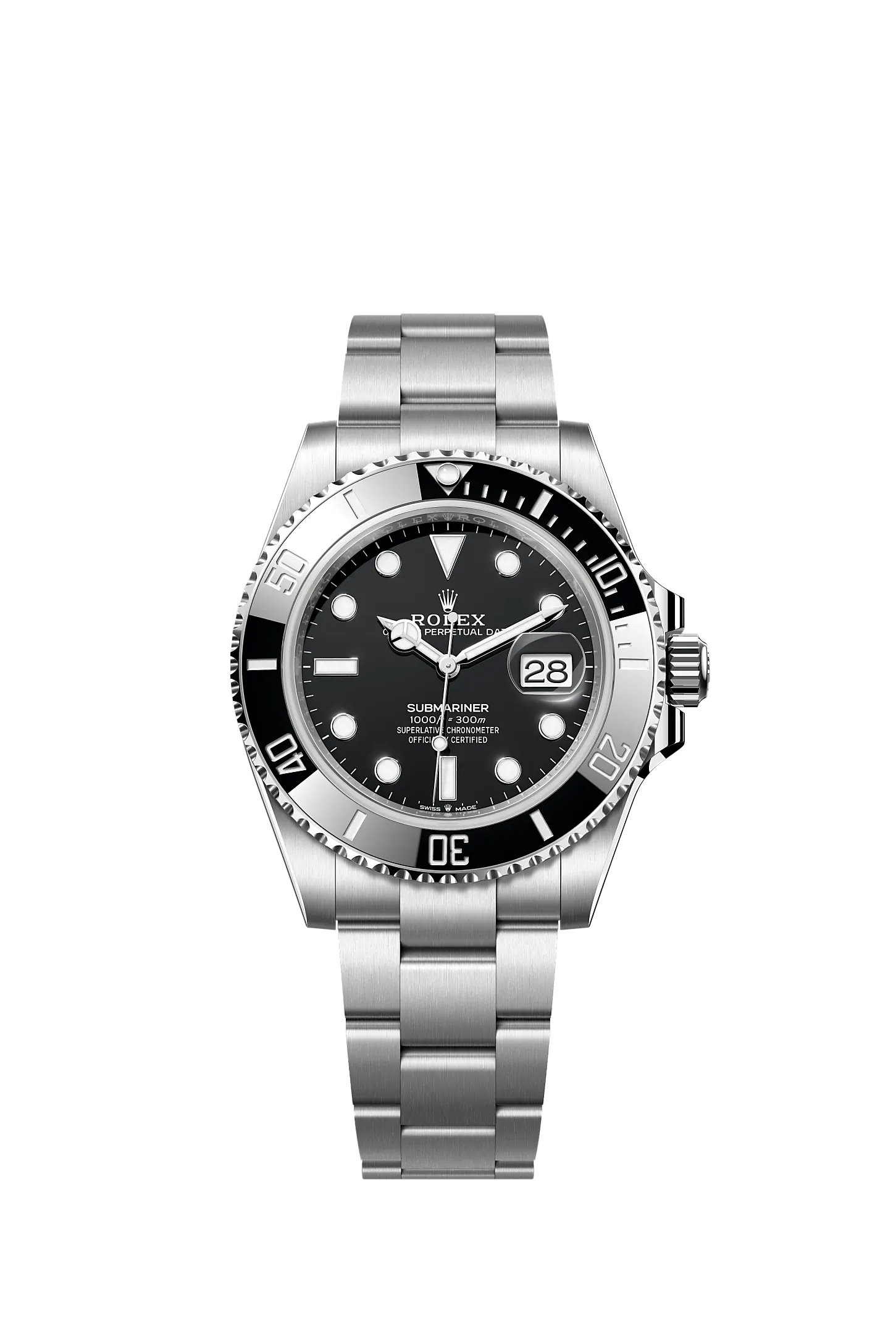
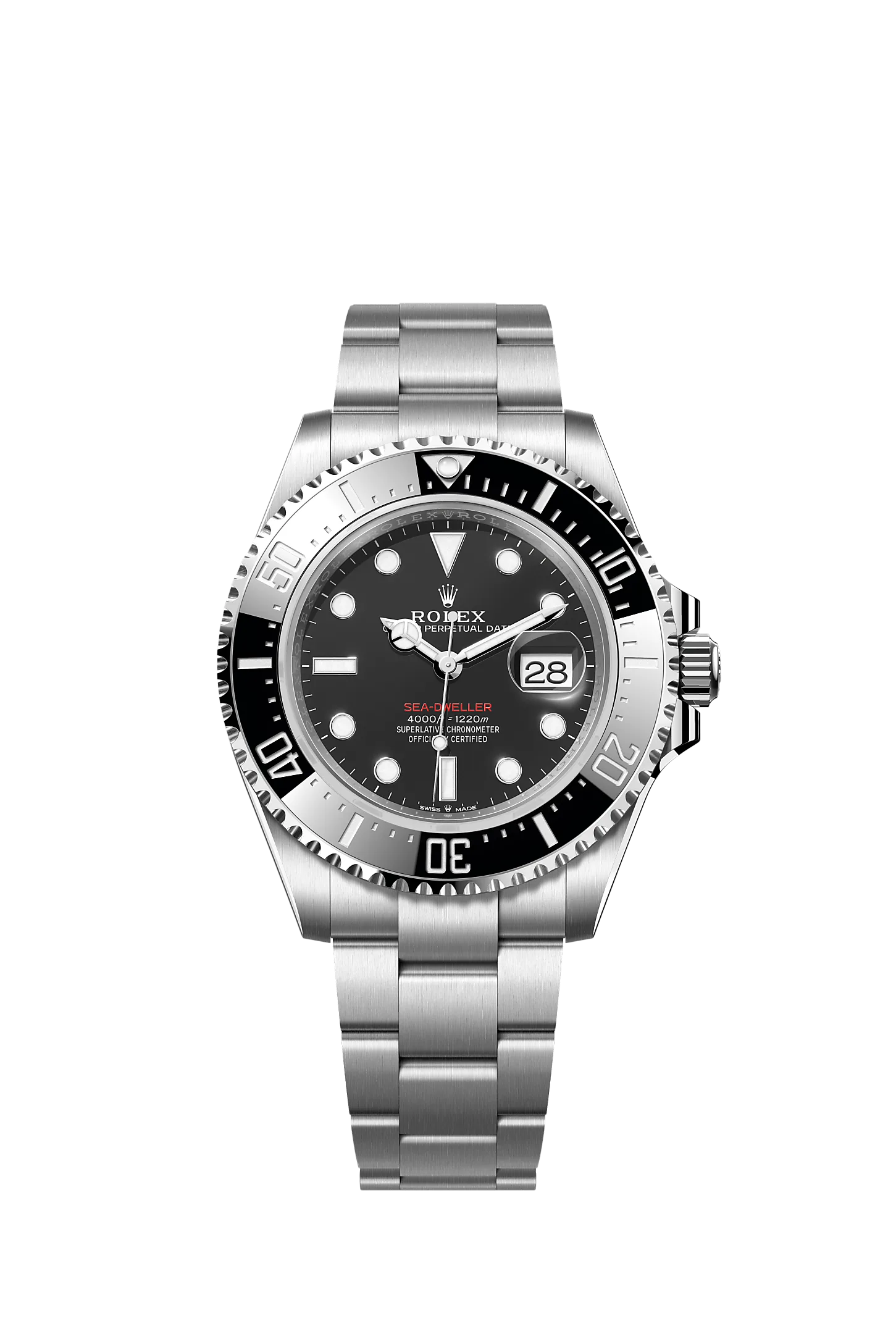
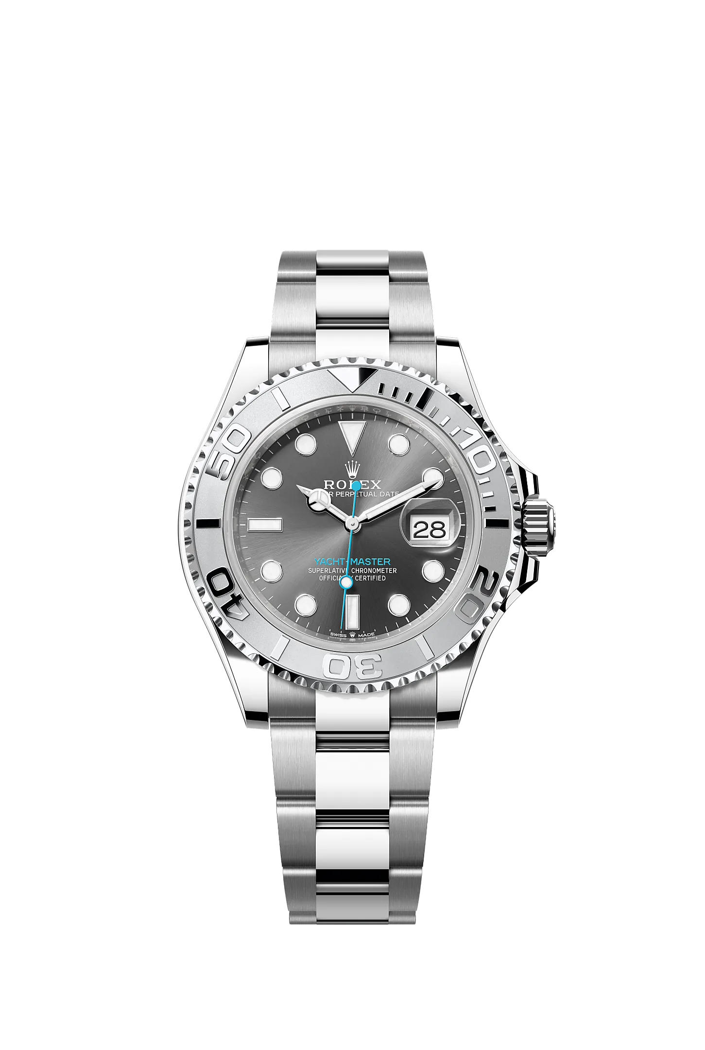
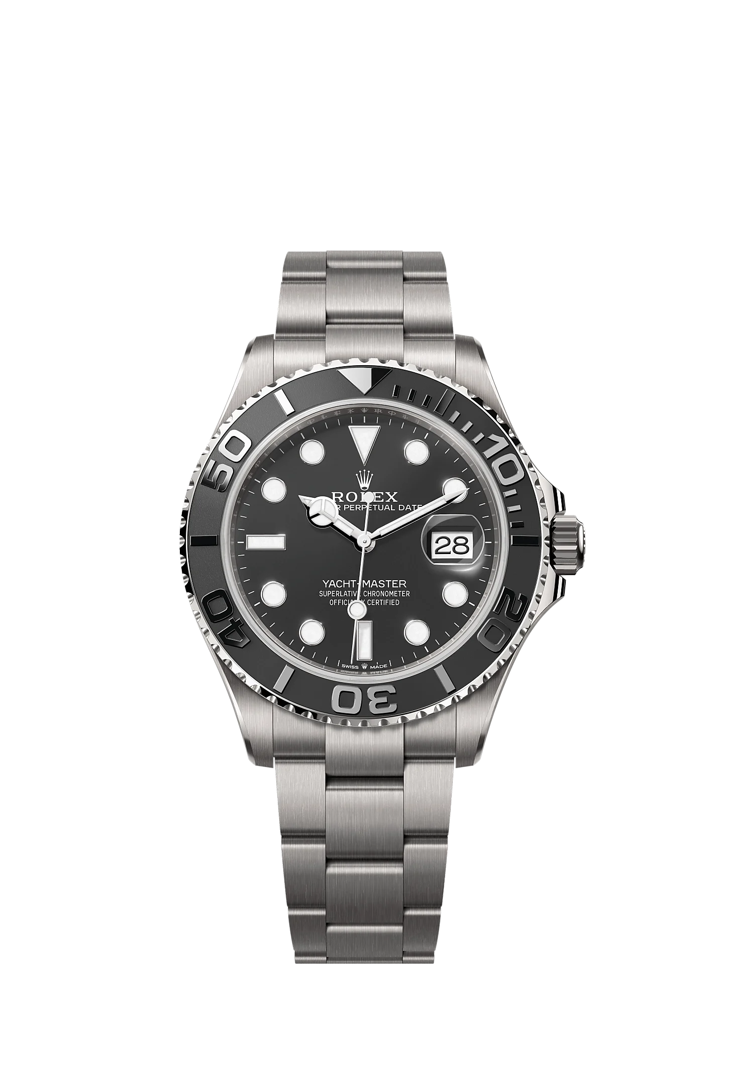
From the Wimbledon Datejust to a titanium Yacht-Master. These five references share the 3235 designation. Explore each watch and its official specifications.

Selected references, not an exhaustive catalogue. Shared calibre designation does not establish identical production revisions. Product imagery © Rolex. Swipe the gallery on smaller screens.

FIRSTHAND FOOTAGE / MANHATTAN WATCH SERVICE

Step onto
the watchmaker’s bench.

A real assembled 3235, shown in a Submariner 126610. Useful for the movement’s visible architecture; this is not footage of a Datejust or proof of a revision match.

Embedded from Manhattan Watch Service on YouTube. If playback is unavailable, watch at the source ↗. Hidden geometry remains unresolved.

THE EVIDENCE, LAYER BY LAYER

LOOK CLOSER.
BUILD FROM WHAT
WE CAN SEE.

A drawing establishes the layers. Service footage provides another view. Each observation becomes a feature we can inspect in the model.

01 / MANUFACTURER ILLUSTRATION

Start with a named calibre.

Our shape baseline is Rolex’s 2016 presentation for calibre 3235. Page 14 separates the automatic winding module into visible layers.

What it gives us

Component silhouettes, openings and a view of the wheel group. It gives us a specific assembly to reconstruct.

It is perspective artwork, so we cannot read exact dimensions from it.

Read the original presentation · p14 ↗
Rolex, Baselworld 2016 · archived by Watchlinks · © Rolex.
AN INTERACTIVE READING OF THE ILLUSTRATION

One reference.
Several discoveries.

ROLEX 2016 / PAGE 14

A bridge is more than an arc.

Four jewel seats, two mounting openings and an asymmetric edge. These visible features replaced the plain arc in our first study.

Their count is visible; model coordinates and thickness are estimated.

Native artwork · © Rolex. Source resolution limits enlargement.

THE SOURCE LEDGER

What each source can tell us.

01 / Manufacturer illustration — geometry baseline

Rolex’s 2016 calibre 3235 presentation shows the exploded module. It supports visible shapes and component groups, but supplies no measured dimensions or tooth-count table.

Open page 14 ↗
02 / Service footage — an assembled cross-check

Manhattan Watch Service shows an assembled 3235 around 3:30. The rotor and visible support arrangement can be compared. Undersides and revision identity remain unresolved.

Return to the film ↑
03 / Teardown account — a mechanical lead

A firsthand 3235 account describes a candidate winding path. Its attachment images were unavailable to us. The text remains a lead for corroboration, not a gear-ratio specification.

Read the account ↗
04 / Rotor underside — input location

A seller photograph attributed to part 3235/3255-570 shows an annular drive around the underside bearing. The model adds a smooth location envelope. Dimensions, teeth, revision match and engagement remain unresolved.

View the seller reference ↗
RESEARCH UPDATE / BENEATH THE BRIDGE

Now we can see
the wheels in place.

A firsthand teardown adds the assembled view we were missing. Compare four photographs to follow the investigation.

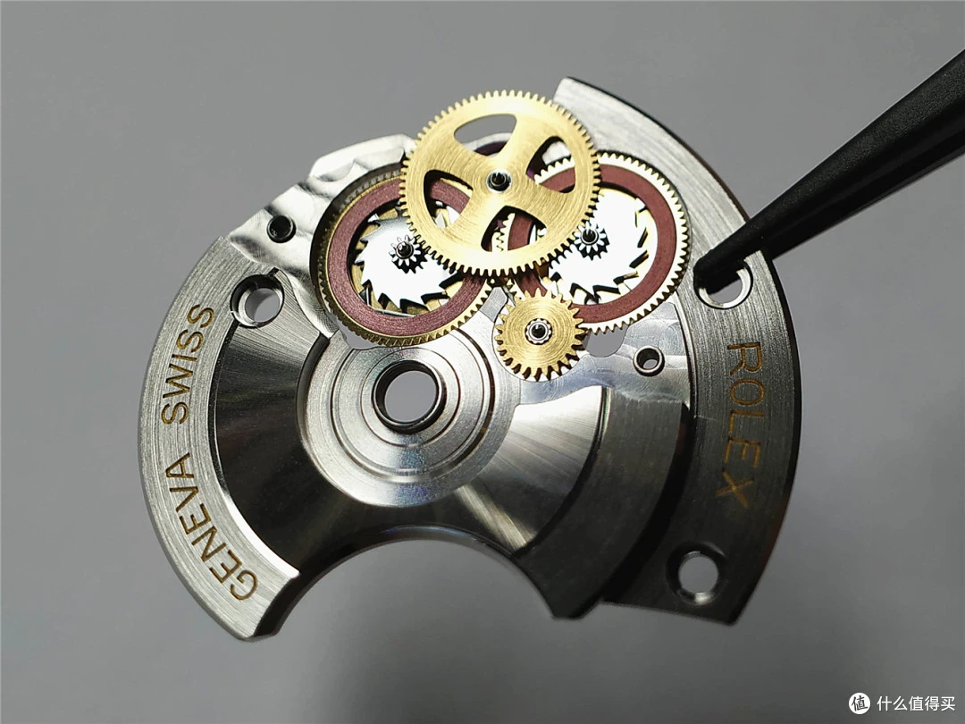
Uncovered automatic winding module photographed during the 2018 Breakingwatch teardown
Photograph: 毒师玩表 / Breakingwatch · 18 July 2018. Read the firsthand teardown ↗
OBSERVATION → MODEL CHANGE

Overlap is a constraint.

The spoked wheel sits above the reversing pair. The smaller wheel lies toward the rotor seat. Our revised layout follows these relative positions.

The view is oblique. It constrains the arrangement, but does not give calibrated axis distances.

01 / CONFIRMED FUNCTION

Either rotor direction can wind.

Rolex confirms this role for the reversing system.

Manufacturer explanation ↗
02 / CANDIDATE CONNECTION

One coupling drives; the other overruns.

The firsthand German teardown describes this sequence. Still photographs support the component groups, not the switching motion.

Teardown account ↗
03 / BEFORE WE ANIMATE

Establish the actual engagement.

The output-shaft match is inferred below. The remaining tooth counts, working engagement and coupling travel remain open. No working gear mesh or winding ratio is claimed yet.

THE NEXT CONNECTION / SHAFT STUDY

ONE SHAFT.
Two views.

Turn the module over. Can we find the same axis again? Follow the proposed correspondences from the visible wheels to the bearings below.

OUTPUT AXIS / HELD-OUT OFFSET
SMALL WHEEL / HELD-OUT OFFSET
Still openTOOTH COUNTS & WORKING MESH
How we checked the correspondence

Three proposed landmark pairs—rotor centre and the two reverser centres—define a mirrored affine alignment. The upper and small-wheel axes are held out of that fit, then compared with the observed underside centres. Offsets are measured in the original 1080 × 810 photographs.

This tests image-space consistency, not dimensions. The views are oblique, the parts occupy different heights, and centres were picked by hand. The closer output-axis match supports a shared shaft; it does not prove hidden construction, tooth counts or a production-revision match.

Photographs © 毒师玩表 / Breakingwatch, 18 July 2018. Original teardown ↗ · Functional account by Erik / Bullit ↗

FROM SMOOTH RIMS TO COUNTED TEETH

Every tooth.
Accounted for.

Count the outer reverser wheel from both sides. Every marker points back to a visible edge in the teardown photographs.

70OUTER TEETH / PHOTO-SUPPORTED STUDY COUNT

Two views from one source. The count now informs our model; the exact tooth profile and working fit are still open.

Photograph: Breakingwatch, 2018. Numbered annotations by Aevo. Original teardown ↗
FOLLOW THE PERIMETER

Check the count.

Step around the rim. The numbers restart in each view; they do not track the same physical tooth when the wheel is flipped.

01 / 70
PAIR FIT / STATIC POSE CHECKED

Larger rims; existing axes. This pose has clearance. The exact tooth profile and running engagement are still unverified.

What the count establishes—and what it doesn’t

The front and back views each support 70 outer teeth after checking the perimeter markers. Automated edge detection also picked up tweezers, reflections and bevel shadows; those detections were reviewed rather than treated as a specification. Both photographs come from the same teardown, so this is a second-view check, not independent provenance.

The model uses this count on both reversers as a shared-part hypothesis. Enlarged outer rims and tooth-to-gap phasing remove the previous separation. The exact radii, tooth flanks, root depth and thickness are fit assumptions; the photograph does not uniquely determine them. Inner pinions, the upper wheel, pitch diameters, coupling motion and winding ratios remain unresolved. Only the displayed static pose is checked. No running mesh or winding animation is claimed.

REFERENCE COMPARISON / PHOTOGRAPH TO MODEL

From the reference to our model.

Service photographs and an isolated parts view separate visible features from provisional reconstruction. Compare the wheels, reverser details and rotor bearing with our actual model.

Link to this layer ↗75 teeth · provisional silhouette
Rolex · Baselworld 2016 · calibre 3235 presentation, page 14. Original embedded artwork, 504 × 912 px; © Rolex. Full source ↗
Current model · scroll to open the layers. Display motion illustrates the construction, not the winding action. Unverified geometry remains estimated.
REFERENCE-BASED / DIMENSIONS ESTIMATED

An assembly, not verified CAD.

The manufacturer illustration establishes visible layers. Scroll-driven separation is for inspection; it is not winding motion.

SOURCE SUPPORT

MODEL ESTIMATES

STILL OPEN

Read the full reconstruction notes

Compare the illustration with the selectable model above. Exploded height is for inspection. The perspective drawing does not supply dimensions or a common scale across layers.

FeatureThis revisionUnresolved
RotorRetained curved windows; continuous outer weight and central collar.Window widths, underside and thickness.
Small bridgeAsymmetric inner edge, two end mounting openings, four separate pierced jewel settings.Exact outline, axis centres, jewels and mounting dimensions.
Lower supportOpen transmission region, central raised seat, stepped support and mounting holes.Recess profiles, underside and alignment with unseen axes.
Bridge fastenersTwo slotted-head envelopes seated in estimated stepped recesses.Thread pitch, dimensions and exact head profiles.
Central attachmentExposed seven-ball bearing study, earlier collar baseline and selectable rotor screw.Raceway grooves, retention, preload, specimen equivalence and fastening profile.
Output shaftInferred common-axis shaft, stepped collar, approximate traced underside pinion and projecting pivot.Hidden shaft profile, teeth, bearing fit and dimensions.
Winding wheelsReverser outer rims: 70 indexed teeth with illustrative profiles. Upper wheel: provisional 75-tooth visual study. Intermediate wheel: approximate traced rim with smooth central pinion envelope.Tooth counts, shafts, engagement and ratios.

Evidence: visible feature counts follow the Rolex illustration; wheel layout and reverser backs also use the 2018 teardown photographs. All model coordinates and depths remain estimates. The service closeup ↗ provides an assembled view; it does not verify the hidden geometry.

FOLLOW THE CONNECTION / RESEARCH UPDATE

Small pinions.
A bigger question.

SELECT A LETTER TO LOOK CLOSER
Photograph: Breakingwatch, 2018. Annotations by Aevo. Original teardown ↗

Read the mechanical account · first post ↗

OUR MODEL / ALIGNMENT CHECKEqual distances. A candidate axis.

Assuming matching inner pinions, the candidate axis now lies equally far from both reversers. The wheel, shaft and bearing openings move together. The photographic match is slightly worse: this is a constrained hypothesis, not a verified correction. These are model units, not Rolex measurements.

BEFORE / CANDIDATE / OBSERVED

A constraint is not proof.

Gold: observed centre. Grey: previous model. Blue: constrained candidate. The front view sets the candidate; the underside is a separate check of this fit using the proposed bearing correspondences.

Source photograph · shown below its native pixel dimensions.
Position differences ×15 · diagram, not image detail.

Centres are approximate, views are oblique, and the bearing identities are proposed. Residuals are image pixels, not machining tolerances. No pinion teeth or working mesh are inferred from equality alone.

WINDING STUDY / INNER PINION

The small teeth.
A count to verify.

NATIVE-SIZE DETAIL / NO UPSCALING

Photograph: Breakingwatch, 2018. Original teardown ↗

PROVISIONAL / NOT A ROLEX SPECIFICATION

11 candidate tips. One usable view.

These markers follow the foreground tooth ends. The darker, offset silhouette underneath is not counted again. Select a number to inspect its location.

The back photograph hides this pinion. The assembled view is too small and partly obscured to settle the count. Accepted count: still open. The 3D model now includes separate pinions using this candidate on both reversers. Their shape and dimensions are illustrative; gear ratios remain unassigned.

FROM WINDING TO STORED ENERGY

Inside the barrel.

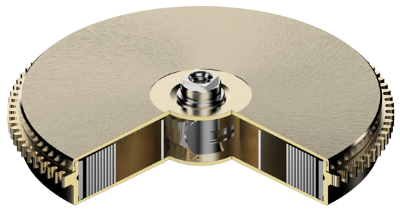
The shell stores the spring; the arbor sits at its centre. Explore a static cutaway based on Rolex’s published architecture, with estimated dimensions and an illustrative spring.

Drag to orbit · scroll to zoom · click a part

Static teaching cutaway · all dimensions estimated · eight illustrative spring turns · attachments and braking details omitted · no winding, torque, power-reserve or installed connection simulation. Selecting the lid restores it; selecting the spring removes it.

Rolex manufacturer cutaway showing the 3235 barrel lid, central arbor, packed spring and toothed rim
Rolex’s original illustration · 2016, page 13. Shown at its native resolution or smaller.
REFERENCE → RECONSTRUCTION

What the drawing gives us.

Observed in the artwork. A covered barrel, central arbor, tightly packed spring and toothed perimeter.

Estimated in our model. Every dimension, surface finish and spring turn. The rim remains smooth until its tooth count is independently checked.

Still open. The spring attachments, braking details and the installed connection to the winding module.

Read Rolex’s technical presentation · p.13 ↗
THE CONNECTION / FUNCTION BEFORE FIT

How winding reaches the spring.

Follow the reported route into the barrel. These symbols explain the roles; their spacing and shapes are not an assembled mechanism.

REPORTED ENGAGEMENTPHYSICAL FIT UNVERIFIED
SPECIMEN ACCOUNT

The module’s output.

The teardown author identifies the pinion beneath the automatic module as engaging the ratchet wheel. This gives us a reported destination for the winding output.

WHAT REMAINS OPEN

The installed axis distance, tooth profiles and working mesh have not been verified. The line above describes a connection, not a measured contact.

Solid line: engagement reported by the specimen account. Dashed line: functional continuation with unresolved mounting geometry. Symbols are illustrative; no rotation or gear ratio is simulated.

Compare the ratchet-wheel specimen with our shape candidate ↗

Erik / Bullit’s specimen teardown · January–February 2023 ↗ · Rolex barrel architecture · p.13 ↗

WHAT THIS STUDY ESTABLISHES

The visible module.
The remaining limits.

OBSERVED · exterior featuresESTIMATED · dimensions and placementUNRESOLVED · fit and operation

The rotor, supports, wheel group, visible fasteners and proposed output shaft are represented. Their shapes follow references; dimensions and hidden connections remain estimates. The winding module is an exterior study; the separate barrel cutaway illustrates supported architecture with estimated internals. Together they remain a partial study, not a reconstruction of the complete 3235 movement.

Assembly check. Layer separation returns to the starting positions, and the upper wheel stays aligned with its output shaft. Static checks nevertheless found solid overlap between the intermediate wheel and a reverser rim, and between the upper wheel and one reverser pinion. The check does not cover every surface or moving contact. The model is not collision-free or mechanically verified.

Deliberately omitted. Reverser pawls and hidden contacts, the concealed rotor attachment, and the separate module-to-movement mounting screw set remain unresolved. The ratchet and barrel-side connection are outside this model. The existing rotor screw, two bridge screws and two small support screws are represented.

Visual reference

Open image ↗

Full image · fitted without enlargement.

Original source ↗